Design of Flat Slab Using Is 456
Abstract
The research work presents the experimental long-term behaviour of reinforced concrete (RC) flat slab specimens at 1:2 scale, subjected to uniformly distributed sustained load in successive phases up to 90 days. The sustained load was applied in two stages, in the first stage, it was 3 kN/m2 for 30 days, whereas in the second stage, it was increased from 3 kN/m2 to 6 kN/m2 for the next 60 days. Age-dependent strength of cement mortar and concrete as used in RC flat slabs has been determined using the method as per the Indian code of practice. The contribution of creep and shrinkage deflection in total deflection for the column strip, middle strip, and cantilever portion has been observed in the range of 34% to 42% at the end of 90 days. After the first 30 days, the mid panel deflection of the flat slabs was larger as compared to column strip and cantilever deflection. At 90 days, the cantilever portion experienced the highest deflection as compared to middle strip and column strip deflection. The measured deflection has also been compared with the IS code procedure and it is found that the code underestimates the long-term deflection of the flat slab. Further, the finite element modelling using ABAQUS has also been carried out on the RC flat slab to validate the experimental results of the same slab within the elastic range. The present study gives an idea to the designer for fixing the thickness of the slab by considering the long-term deflection criteria in the design of the RC flat slab based on its behaviour under sustained loading.
Introduction
The reinforced concrete (RC) flat slab is a thin structure concerning its span length and the design is mainly governed by stiffness rather than strength. The deflection in the RC slab mainly depends on the non-linear and inelastic properties of concrete. Nowadays, the flat slab floor system is considered one of the most popular forms of construction due to its easiness in construction with a comparatively lower cost. The engineers and designers are mainly focusing to design efficient slab which has larger spans. Flat slabs have a variety of practical applications in various fields such as in different floor situations, ramps, irregular column layouts, etc. The advantage of the flat slab over other slab includes flexibility in plan and column layout, lesser depth, reduced dead weight, and faster rate of construction. The flexibility of flat slab construction results in economical construction with more freedom to the architect and designers. It provides easy formwork arrangement, plain ceiling surface with a better diffusion of light and larger head-room or shorter storey height with pleasing appearance e.g. large halls, library, commercial building, etc. Few experimental and analytical studies were conducted to measure the long-term deflection of RC slabs (i.e. one-way, two-way, flat slabs, etc) with different concrete mix proportions.
Nilson and Walters [1] investigated the two-way slab deflections using an equivalent frame method and compared it with ACI-209 [2] and found that the results obtained from the equivalent frame method are comparable with the method given in ACI-209 [2]. Abdalla et al. [3] performed an analysis of the experimental results obtained by testing eight one-way concrete slabs reinforced with glass-fiber and carbon-fiber and plastic rebars along with steel reinforcement. Four-point static loading arrangement was employed to investigate the flexural behavior of the slabs. A good agreement was obtained between the experimental results and the results obtained through the proposed methods of analysis. Sherif and Dilger [4] compared the maximum deflection of the continuous flat slab by analyzing the various methods i.e. equivalent frame method, the direct design method, the prismatic member method, and the finite element method. It was found that analytically calculated values of deflections have differed from experimental results. Gilbert [5] calculated the deflection of the slab with the help of two country design codes (American and Australian) and demonstrated the deficiencies in the different approaches. A simplified deflection calculation procedure was proposed and the changes in the available methods were suggested. Nayak and Menon [6] conducted a research study on one-way slabs and compared the deflections obtained by the different methods of the various design codes. It was found that various limitations were there in the prediction of the cracking moment, moment-curvature, and load-deflection behavior. Gilbert and Guo [7] conducted the experimental investigation on RC flat slabs to evaluate the time-dependent deflection, strains, and cracking pattern under uniformly distributed load for the period up to 750 days at different loading conditions. On comparing the deflections with the codal provisions [2, 8, 9], it was observed that the code greatly underestimates the experimental time-dependent deflections at all the loading conditions. Govind et al. [10] studied the deflection provisions given in various design codes and calculated the two-way RC slab deflections using provisions given in Indian code IS 456 [8]. It was observed that the Indian code provisions are not adequate to estimate the two-way RC slabs deflection and therefore, these provisions need to be modified. Varma and Pendharkar [11] presented a rational approach for estimating short-term deflection in two-way RC slabs with the help of the equivalent load method. A good agreement was observed between the values of deflections obtained experimentally as well as those obtained through the newly proposed method. Vittorio [12] studied the long-term behavior of steel reinforced slabs particularly focusing the effects of creep and shrinkage. It was found that the deflections differ quite a lot between the two slabs, one subjected to both shrinkage and creep effects, and others already experienced shrinkage effects for several weeks. Varma et al. [13] proposed a procedure to determine the deflection in the concrete structure and validated it with the experimental data available in the literature and the design codes procedure for deflection calculations. It was found that the experimental results did not agree with the results obtained analytically. Yan et al. [14] performed an experimental investigation on the ultra-lightweight flat slabs to determine the load-deflection behavior. Analytical models were developed to predict the punching shear resistance of lightweight flat slab. Tovi and Goodchild [15] measured the deformation of multistory building flat slabs and found that these slabs showed good serviceability under the gravity loads. Torabian et al. [16] tested different RC flat slab under concentric loading and concluded that the deflection of the slabs was affected by the flexural and shear reinforcement. Gutkowski et al. [17] developed an analytical model to measure mid-panel deflections of the RC flat slab. The results were found to be in good agreement with the published experimental results. Kuznetsov and Shaposhnikova [18] determined the effect of the prestressed reinforcement on the deflection of flat slabs and observed that the use of high-strength reinforcement without adhesion to concrete reduced the deflections at the center of the slab. Majtanova and Halvonik [19] conducted the numerical investigation on the flat slab and developed a non-linear material model for the measurement of the deflection of slabs. It was further observed that the flat slabs constructed using high strength concrete experienced lesser deflection and showed more resistance against the ultimate load in the tension zone [20]. Hossain et al. [21] predicted short and long term deflection of the flat slab using an artificial neural network (ANN). The span length, dead load, live load and compressive strength were considered as input parameters. Gayed and Ghali [22] also presented an analytical approach for predicting the long-term deflections of two-way concrete floor slabs. Kim et al. [23] reported that the load-deflection behavior of the flat slab cast with a textile-reinforced concrete panel was greatly increased as compared with the conventional flat slab. Wang et al. [24] conducted a detailed investigation on the time-dependent deflection of composite slab made with normal and recycled aggregate concrete and supported on fixed and simple supports. The experimental results were compared with the results obtained from finite element modeling and found in good agreement. Past studies show that the experimental values of deflections are not truly satisfying the deflections obtained by the various analytical methods. Longer and shorter spans are giving different values of deflections for the same slab and under the same parameters. Also, the procedures suggested by the design standards and the analytical solutions adopted for the calculation of creep and shrinkage are not satisfying the criteria properly and hence considerable deviation from the experimental results.
The present study is therefore planned to collect data on experimental measures of long-term deflection due to the combined effect of creep and shrinkage of concrete. The experimental program involved the testing of RC flat slab specimens having plan dimensions of 2100 × 2100 mm and thickness of 70 mm and tested under two stages of sustained uniformly distributed gravity loads i.e. 3 kN/m2 (i.e. loading stage-1 for one month) and 6 kN/m2 (i.e. loading stage-2 for next two month) for three months. Finite element analysis (FEA) by using ABAQUS software has also been carried out to validate the experimental elastic response of flat slab. This type of work though requires more time but effort to get meaningful and useful results may help engineers and designers in developing enough confidence by knowing the time-dependent behavior of the flat slab.
Experimental investigation
Materials
The material used for preparing the concrete mix was procured from the local market. Ordinary Portland cement (OPC) of 43 grade was selected for the present investigation. Locally available river sand and the 16 mm (maximum) size of quartzite crushed stone coarse aggregate were used as fine and coarse aggregates respectively. High yield strength deformed (HYSD) steel bars of 6 mm nominal diameter in both directions were used as reinforcement in the RC flat slab. The physical properties of cement, fine aggregate, coarse aggregate and reinforcing bars are given in Table 1. The table shows that the materials used conformed to the relevant standard specifications prescribed by Indian standard codes [25,26,27,28].
Full size table
Concrete mix
The concrete mix was designed using the method of trials according to the guidelines of IS 10262 [29]. The quantities of ingredients for one cubic meter of concrete were calculated by using the absolute volume method. The concrete mix proportion for casting standard specimens and RC flat slabs such as cement, fine aggregate, coarse aggregate, and w/c ratio was designed and decided as 400 kg/m3, 600 kg/m3, 1200 kg/m3 and 0.55 respectively. The average slump of concrete prepared was measured as about 60 mm.
Details of casting and curing of standard specimens and RC flat slabs
The standard concrete cubes of size 70.6 mm and 150 mm and prisms of size 100 × 100 × 500 mm as per Indian Standards [25, 30] were prepared for the determination of compressive strength of cement mortar and concrete and flexural tensile strength of concrete respectively. After 7 days and 28 days of curing, five cubes of mortar & concrete and five prisms were tested under compression and flexural testing machine as available in the department. The remaining samples were taken out from the curing tank and stored at ambient temperature and tested at the age of 60 and 90 days. The specimens were tested in accordance with IS 4031 [25] and IS 516 [30] for mortar strength (Fig. 1) and compressive and flexural tensile strength (Fig. 2) respectively at all ages. The strength results have been presented based on the average of five samples.

Cement mortar cubes and the failure pattern of the tested cube
Full size image
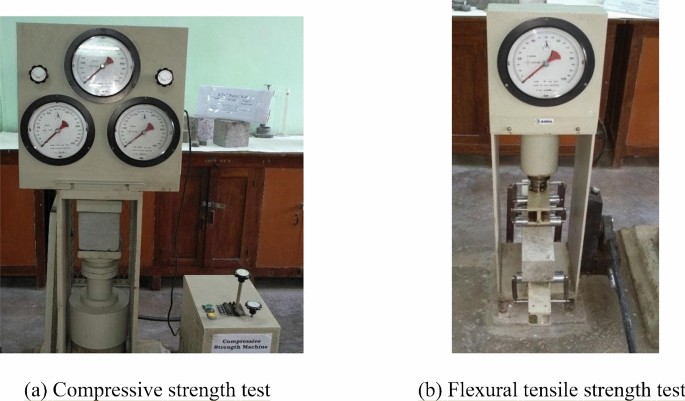
Testing of the specimen under compression and four-point loading for flexure. (a) Compressive strength test; (b) Flexural tensile strength test
Full size image
Two RC flat slabs were cast in the heavy structural laboratory of the department. Each slab has an overall plan dimension of (2100 × 2100 mm) with an overhang of 350 mm on all the four edges. The flat slabs were supported on square brick columns having a cross-section dimension of 230 × 230 mm and a height of 750 mm. The center to center distance between the columns was 1400 mm. The supporting columns were fixed at the base. Slabs were of uniform thickness of 70 mm throughout with a nominal effective cover of about 20 mm. The HYSD bars were placed at a spacing of 150 mm c/c and alternate bars were bend upward at a distance of 280 mm i.e. (0.2 times l) from the face of the column in both horizontal directions, where 'l' is the center to center distance between the columns. The schematic diagram of the flat slab with reinforcement detail is shown in Fig. 3. Bars crossing each other were secured by annealed binding wires (0.9 mm diameter approximately) at intervals, in such a manner that they did not slip over each other during concreting. The bars were free to act along with concrete in the direction in which they were provided without any lateral restraint. Figure 4 shows the plan view of reinforcement detailing and casting steps of RC flat slabs. After concreting, the curing by ponding was done on the top surface of the slabs. The slab borders were covered by the fine sand and water was poured and cured for 28 days. The curing arrangement of the RC flat slab is also shown in Fig. 4.
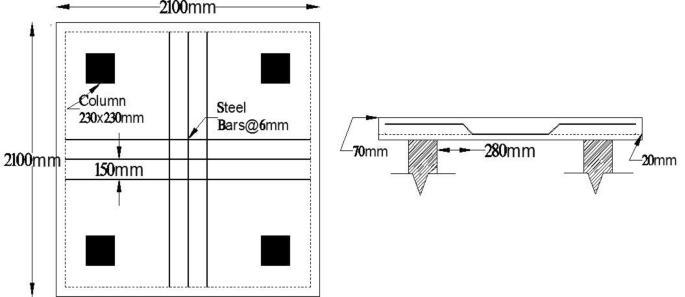
Details of RC flat slab
Full size image
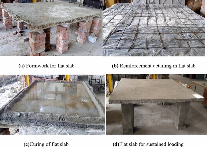
Casting and curing of RC flat slab
Full size image
Testing of RC flat slab under sustained loading
After 28 days of curing by ponding, flat slabs were ready for sustained loading. Five dial gauges were placed in each slab at different locations. Two dial gauges were placed at the cantilever portion, two dial gauges were placed in the column strips and one dial gauge was placed in the middle of the slab. These dial gauges were placed on the iron girder so that they remain fixed at the bottom by the magnetic base. Figure 5 shows the position of dial gauges with a schematic view under flat slabs. The uniformly distributed sustained load on the flat slabs was maintained with the help of concrete blocks and bricks. Each concrete block and brick was weighed and then carefully positioned to simulate a uniformly distributed load on the slab. The arrangement of sustained loading for the first and second stage i.e. 3 kN/m2 and 6 kN/m2 is separately shown in Fig. 6a and b, respectively. The first stage loading was continued for one month followed by second stage loading for a further 60 days i.e. a total of 90 days. Thus, this testing was continued for three months and the total deflection (i.e. deflection due to self-weight + instantaneous + creep + shrinkage) was recorded at suitable intervals. The values of total deflection have been presented below based on the average of two specimens reading.
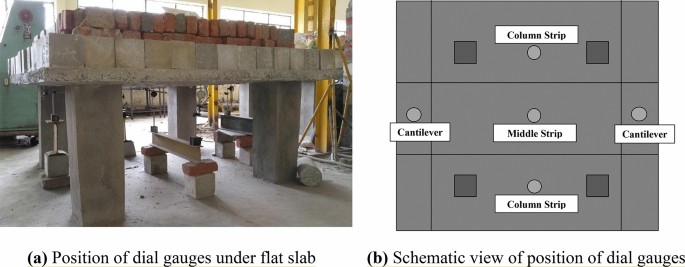
Position of dial gauges with schematic view under RC flat slab
Full size image
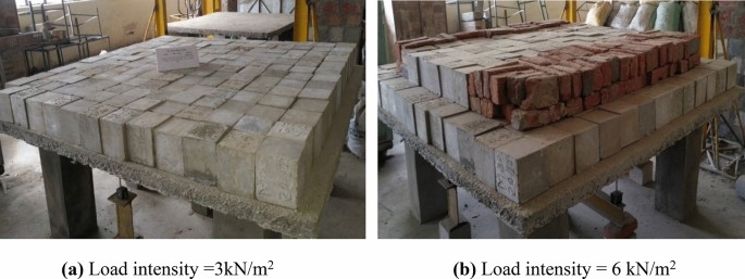
Successive sustained loading stages on RC flat slab
Full size image
Experimental results
The compressive strength of cement mortar is the most important parameter among all the properties of materials as far as the design strength of concrete is concerned. Therefore, the cement is always tested for its strength before the same is used in concrete construction. The compressive strength development in cement mortar and in concrete with age is as shown in Fig. 7a and b, respectively. The strength of the cement mortar cubes and concrete cubes is compared with the calculated strength as per the empirical relation given in SP 24 [31]. The development of flexural tensile strength of concrete with age is also shown in Fig. 7c.
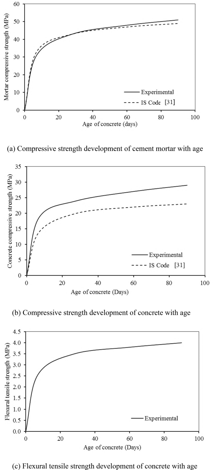
Compressive and flexural tensile strength development of mortar and concrete with time
Full size image
The graphical representation of the total deflection (including instantaneous, creep, and shrinkage deflection) of RC flat slab at different positions i.e. at the middle strip, column strip and cantilever strip and its comparison with the values obtained from IS 456 [8] procedure for the prediction of long term deflection of RC members are plotted in Fig. 8a, b, c, respectively.
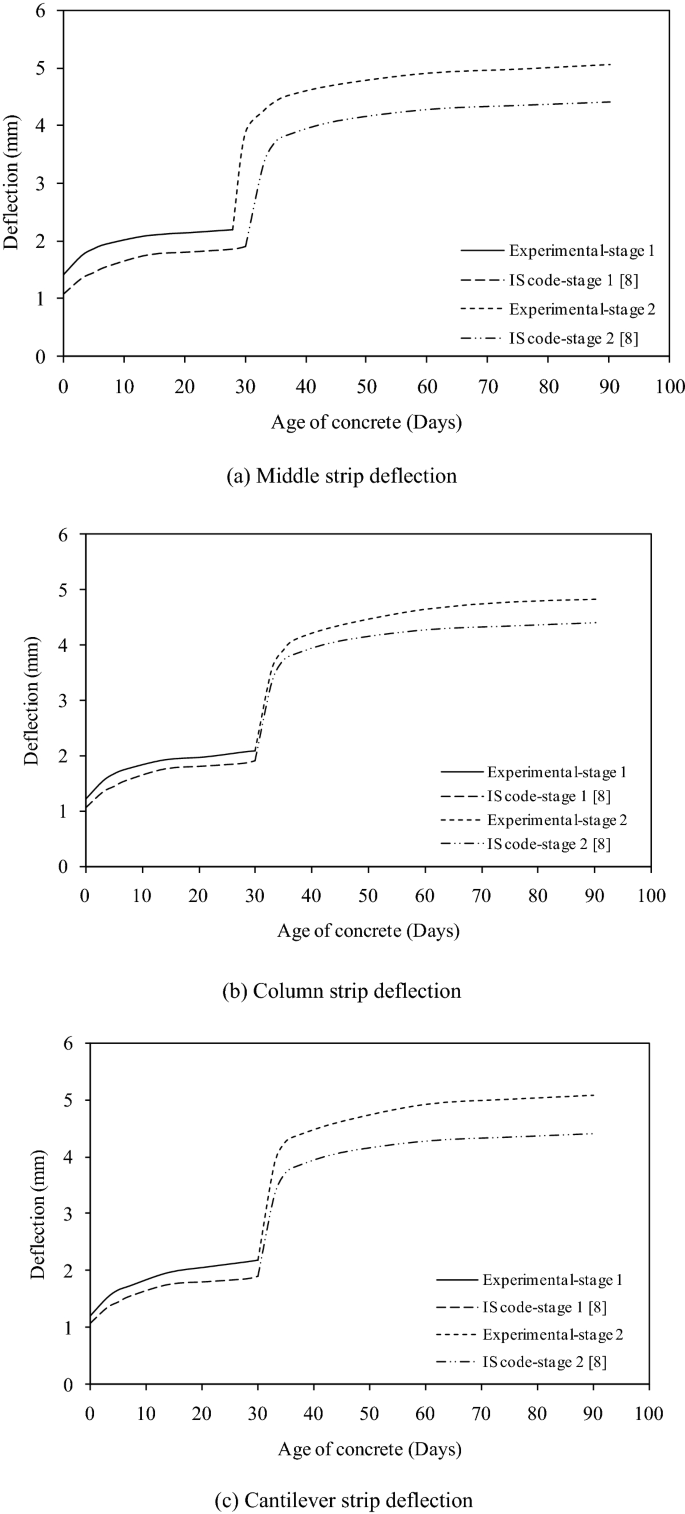
Long-term deflection of RC flat slab at different positions and phases of sustained load
Full size image
Discussion of the results
Age-dependent strength of mortar and concrete
It can be seen in Fig. 7a that the compressive strength of cement mortar increased consistently with time and the magnitude of strength is close with values predicted by using the IS code model. It can be seen that the early strength of mortar up to 7 days is lower than the IS code values. In 7 days, the cement mortar gains strength about 72% of the strength of 28 days whereas IS code strength is about 75% of the strength of 28 days, and the strength development after 28 days is almost the same. The mortar cubes keep gaining strength after 28 days and the percentage variation between experimental values and IS code values are about 4% at the end of 90 days. Four compounds are present in cement i.e. tricalcium silicate (C3S), di-calcium silicate (C2S), tri-calcium aluminate (C3A), and tetra calcium alumino-ferrite (C4AF). The two most important compounds responsible for achieving the strength are C3S and C2S which constitutes about 70%–80% of cement. More heat of hydration is produced when C3S reacts with water and it is responsible for the early strength of concrete whereas C2S hydrates rather slowly and provides later strength of concrete due to a smaller amount of heat of hydration. The cementitious property is due to the formation of dense calcium silicate hydrate with a higher specific surface.
It is observed from Fig. 7b that at the age of 7 days, the gain in compressive strength of concrete is about 78% of its 28 days strength whereas IS code strength is about 70% of its strength at 28 days. The percentage variation of strength development after 28 days is around 20%. The concrete cubes keep gaining strength even after 28 days with the percentage variation in the increase in experimental and IS code values of about 26% at the end of 90 days.
The flexural strength of concrete was observed as 8%–11% of the compressive strength of the concrete for higher mixes of concrete (25 MPa or more) and 9%–12.8% for lower mixes of concrete (less than 25 MPa). It has been observed that the flexural tensile strength of concrete is increasing at a rapid rate at an early age but with the passage of time, the rate of development becomes slow. Since, the compressive strength of concrete increases with age due to continued hydration process, the rate of gain of this strength is more during initial days and it gets slow with time.
Long-term deflection of RC flat slab
Long-term deflections have been observed at the middle strip, column strip, and cantilever portion for two different stages of loading conditions i.e. 3 kN/m2 and 6 kN/m2. The percentage variations of the instantaneous deflection in different portions of the slab at load intensity of 3 kN/m2 and 6 kN/m2 are about 60% for the middle strip, 62% for column strip, and 64% for cantilever. For the first stage of loading of load intensity of 3 kN/m2, the increase in the development of creep and shrinkage deflection is about 56% for the middle strip, 77% for column strip, and 82% for cantilever as compared with initial elastic deflection. For the second stage of loading of load intensity of 6 kN/m2, the increase in the development of creep and shrinkage deflection is about 40% for the middle strip, 50% for column strip, and 52% for cantilever as compared with initial elastic deflection. The cantilever portion experienced the highest downward deflection followed by a middle strip and column strip. The deflection due to creep and shrinkage was also incorporated with time.
Comparison between theoretical and measured deflection
The values obtained theoretically by using the formulae of deflection given in IS 456 [8] are tabulated in Table 2. The final deflection of each specimen was found larger than that predicted as per IS code. Various environmental factors affect the deflection of the slabs due to which the difference in the code and experimental values exists. On the comparison between experimental and code values of the deflection of the flat slabs after 1 month for loading stage-1, it is seen that the percentage variation is about 9% for column strip, 14% for middle strip and 13% for cantilever and whereas for loading stage-2, the percentage variation after 90 days is about 8% for column strip, 12% for middle strip and 13% for cantilever as compared with measured deflection.
Full size table
Contribution of creep and shrinkage deflection in total deflection
The contribution of creep and shrinkage deflection obtained after deducting instantaneous values from total deflection of RC flat slab is given in Tables 3 and 4 for loading stage-1 (i.e. 3 kN/m2) and loading stage-2 (i.e. 6 kN/m2) respectively at different ages varying from 6 hrs to 90 days. The total deflection of the slab includes the effect of self-weight, elastic deflection, creep, and shrinkage. The experimentally observed data shows that the contribution of creep and shrinkage deflection in total deflection is increased with age. For the first stage of loading, at 30 days, more than 45% part of total deflection is due to the creep and shrinkage of concrete only. The ratio of creep plus shrinkage deflection to initial elastic deflection at 30 days for column strip, middle strip and cantilever strip is 0.77, 0.82, and 0.56 respectively. For loading stage-2, the contribution of creep and shrinkage deflection to total deflection at 90 days is varied between 34% to 42%. The data also shows that the ratio of creep and shrinkage deflection to initial elastic deflection is observed higher with an increase in time. It is also observed that the rate of gain in this ratio is more at an early age. Thus, a significant effect of creep and shrinkage deflection in total deflection of the RC flat slab has been observed. The possible factors which influence creep and shrinkage deflection in the slab are the volume of cement paste, compositions of concrete, 28 days strength of concrete, age of loading, and the magnitude of the load.
Full size table
Full size table
Finite element modelling of RC flat slab
The behaviour of the RC flat slab was predicted with the help of the ABAQUS structural analysis modelling tool. The Finite element model (FEM) of the flat slab is shown in Fig. 9. All the basic properties of concrete and steel used in the flat slab were given as input parameters in the ABAQUS program to carry out the analysis. The concrete damaged plasticity (CDP) model was used to describe the behavior of concrete under sustained loading which has a higher potential for convergence in comparison to other models. In addition to the basic parameters, some other parameters were also given in the computer program to describe the microstructure of the concrete such as dilation angle (φ), plastic potential eccentricity (e), initial biaxial/uniaxial ratio (fbo/fco), the shape of the loading surface (Kc) and viscosity parameter. The dilation angle (φ) i.e. internal friction angle of concrete was taken as 37 degrees throughout the numerical simulation. The ratio of the tensile to compressive strength of concrete was taken as 0.1 which is known as plastic potential eccentricity (e). The ratio between the initial compressive yield stress i.e. biaxial and the uniaxial stress was provided as 1.16 as recommended by the ABAQUS manual. The value of Kc was taken as 2/3 during the analysis and the viscosity parameter was specified as zero. The same mesh size was assigned to the elements in the FEM so that different materials contributed to the same node.
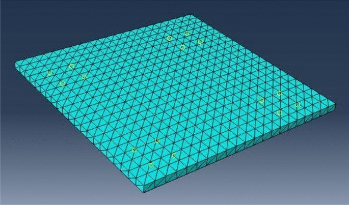
FEM model of RC flat slab
Full size image
The deflection pattern of the flat slab under loading in the ABAQUS program is shown in Fig. 10. The middle portion indicated by red colour undergoes maximum deflection followed by column strip with yellowish colour and cantilever with green colour. The elastic deflections of cantilever, middle, and column strips were obtained through FEM and its comparisons are shown in Fig. 11. It has been observed that the elastic deflection of the middle strip is quite similar to the values obtained experimentally. However, the elastic deflections of the column and middle strips have slightly deviated. The FE model experienced lower deflections in the cantilever region unlike experimental results for both the intensities of load.
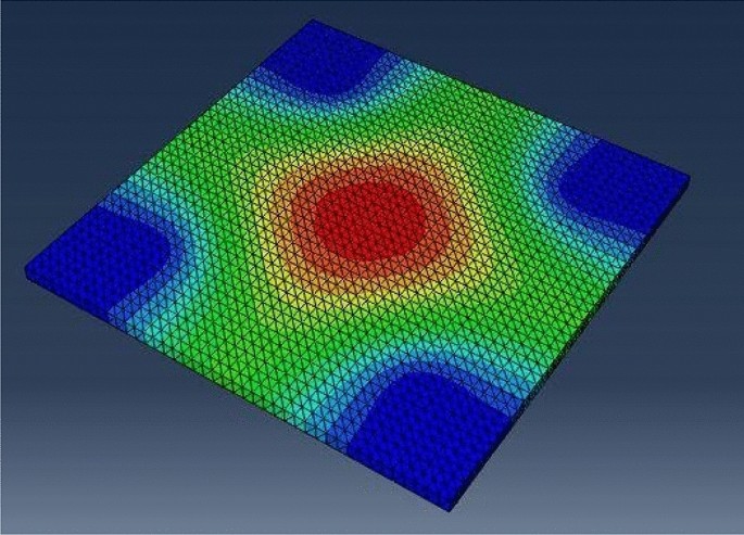
Deflection pattern of RC flat slab using FEM
Full size image
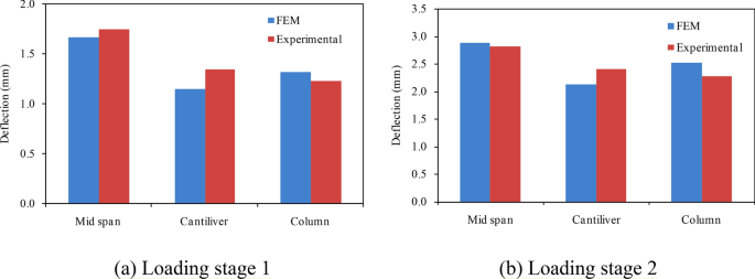
Comparison of experimental elastic deflection with the FEM results. (a) Loading stage 1; (b) Loading stage 2
Full size image
Conclusions
The present experimental and analytical investigation describes the long-term behavior of RC flat slab under sustained loading. Age-dependent strength of mortar and concrete at ages varying from 7 to 90 days was also studied. The flat slabs of size 2100 × 2100 mm in plan dimensions and 70 mm cross-section were cast and tested under successive sustained uniformly distributed floor load up to 90 days. The long-term deflection of the middle, column and cantilever portions of flat slab has been recorded. Finite element modeling using ABAQUS for the elastic response of flat slab was also carried out to predict the behavior of tested slab specimens.
The compressive and flexural strengths of the mortar and concrete are found to be consistently increasing with the time and the results are found in good agreement with the IS predicted model. The maximum deflection of the slab increased rapidly over the first two or three days of loading, with about 50% of the total deflection occurring within 3 to 7 days of initial loading. In the successive sustained loading on flat slab, the cantilever portion experienced maximum creep and shrinkage deflection than the middle and column strips. However, the middle strip undergoes the highest instantaneous deflection at the time of loading. The contribution of creep and shrinkage deflection for the first stage of loading has been observed as 36 to 45% whereas for the second loading stage, these contributions varied as 34 to 42%. The elastic deflections of the cantilever, column, and middle strips of the flat slab are also compared with the values predicted by FE model by ABAQUS and it has been found in good agreement with the experimental values. But, the long-term deflection of the flat slab predicted by the IS code procedure underestimates the experimental values of deflections at all positions.
The present study will be helpful for the designer to have an idea about the thickness of slab required by considering the long-term deflection criteria in the design of the RC flat slab subjected to sustained loading. A more comprehensive study on the long-term behavior of flat slab with variables such as different sizes of flat slab, different types of concrete containing admixtures, percentage of steel, duration, and magnitude of sustained loading is required for the comparison with regard to the recommendation of different codes of practices and establish the long-term behaviour in more rational form.
References
- 1.
Nilson AH, Walters DB (1975) Deflection of two-way floor systems by the equivalent frame method. J Proc 72(5):210–218. https://www.concrete.org/publications/internationalconcreteabstractsportal/m/details/id/111
- 2.
ACI Committee 209 (1999) Prediction of creep and shrinkage, and temperature effects in concrete structures. American Concrete Institute, Farmington Hills (MI)
- 3.
Abdalla H, El-Badry MM, Rizkalla SH (1996) Deflection of concrete slabs reinforced with advanced composite materials. In Proceeding of the 2nd International Conference on Advanced Composite Materials in Bridges and Structures, pp 201–208. https://trid.trb.org/view/655880
- 4.
Sherif AG, Dilger WH (1998) Analysis and deflections of reinforced concrete flat slabs. Can J Civ Eng 25(3):451–466. https://doi.org/10.1139/l97-102
Article Google Scholar
- 5.
Gilbert RI (1999) Deflection calculation for reinforced concrete structures—why we sometimes get it wrong. Struct J 96(6):1027–1032 https://www.concrete.org/publications/internationalconcreteabstractsportal/m/details/id/779
Google Scholar
- 6.
Nayak SK, Menon D (2004) Improved procedure for estimating short term deflections in RC slabs. Indian Concr J 78(7):19–25
Google Scholar
- 7.
Gilbert RI, Guo XH (2005) Time-dependent deflection and deformation of reinforced concrete flat slabs-an experimental study. ACI Struct J 102(3):363
Google Scholar
- 8.
IS 456 (2000) Code of practice for plain and reinforced concrete. Bureau of Indian Standards, New Delhi
- 9.
AS3600 (2001) Concrete structures code. Standards Association of Australia, Sydney, Australia
- 10.
Govind M, Sarkar P, Menon D (2008) Short term deflections in two way RC slabs using deflections coefficients. J Struct Eng 35(4):247
Google Scholar
- 11.
Varma M, Pendharkar U (2010) Equivalent load method for short-term deflection of simply supported two-way RC slabs. Int J Earth Sci Eng 3(3):685–690
Google Scholar
- 12.
Vittorio SD (2011) Time-dependent behaviour of reinforced concrete slabs. Alma Mater Studiorum-University of Bologna Faculty of Engineering, International Master Course in Civil Engineering, DICAM, Civil, Environmental and Materials Engineering, Advanced Design of Structures Thesis
- 13.
Varma M, Pendharkar U, Sharma RK (2012) Experimental study to evaluate short-term deflections for two-way RC slabs. Int J Civ Struct Eng 2(3):901–913. https://doi.org/10.6088/ijcser.00202030018
Article Google Scholar
- 14.
Yan JB, Wang JY, Liew JR, Qian X, Zhang W (2016) Reinforced ultra-lightweight cement composite flat slabs: experiments and analysis. Mater Des 95:148–158. https://doi.org/10.1016/j.matdes.2016.01.097
Article Google Scholar
- 15.
Tovi S, Goodchild C (2017) Deformation of multi-storey flat slabs, a site investigation. Adv Concr Constr 5(1):49–63. https://doi.org/10.12989/acc.2017.5.1.49
Article Google Scholar
- 16.
Torabian A, Isufi B, Mostofinejad D, Ramos AP (2019) Behavior of thin lightly reinforced flat slabs under concentric loading. Eng Struct 196:109327. https://doi.org/10.1016/j.engstruct.2019.109327
Article Google Scholar
- 17.
Gutkowski RM, Miller NJ, Fragiacomo M, Balogh J (2011) Composite wood-concrete beams using utility poles: time-dependent behavior. J Struct Eng 137(6):625–634. https://doi.org/10.1061/(ASCE)ST.1943-541X.0002052
Article Google Scholar
- 18.
Kuznetsov V, Shaposhnikova Y (2018) Deflections of slabs of monolithic flat ceilings with high-strength reinforcement without adhesion to concrete. In XXIst International Scientific Conference on Advanced in Civil Engineering: Construction-The Formation of Living Environment, FORM 2018, pp 062018–062018. https://doi.org/10.4028/www.scientific.net/SSP.292.134
- 19.
Majtánová L, Halvonik J (2019) Numerical analysis of the experimental flat slabs. In: Solid state phenomena, vol 292. Trans Tech Publications Ltd, pp 134–139. https://doi.org/10.4028/www.scientific.net/SSP.292.134
- 20.
Makki RF, Alalikhan AA, Al-Katib HA (2019) Load-deflection behaviour of hybrid concrete flat slab. Przegląd Naukowy. Inżynieria i Kształtowanie Środowiska 28(4(86)). https://doi.org/10.22630/PNIKS.2019.28.4.47
- 21.
Hossain TR, Ahmed SU, Siddiquee MS (2019) Prediction of short-and long-term deflections of reinforced concrete flat plates using artificial neural network. J Civ Eng (IEB) 47(2):167–177 http://www.jce-ieb.org/doc_file/4702007.pdf
Google Scholar
- 22.
Gayed RB, Ghali A (2019) Control of long-term deflection of concrete slabs by prestressing. Struct Concr 20(6):1816–1827. https://doi.org/10.1002/suco.201800340
Article Google Scholar
- 23.
Kim HY, Koh KT, You YJ, Ryu GS, Seo DW, Jin SS, Ahn GH, Nam JH (2020) Load-deflection behaviour of concrete slab-type elements cast on stay-in-place TRC formwork. Compos Struct 29:112310. https://doi.org/10.1016/j.compstruct.2020.112310
Article Google Scholar
- 24.
Wang Q, Yang J, Liang Y, Zhang H, Zhao Y, Ren Q (2020) Prediction of time-dependent behaviour of steel–recycled aggregate concrete (RAC) composite slabs via thermo-mechanical finite element modelling. J Build Eng 29:101191. https://doi.org/10.1016/j.jobe.2020.101191
Article Google Scholar
- 25.
IS 4031 Part 1 to 15 (1999) Indian standard methods of physical tests for hydraulic cement. Bureau of Indian Standards, NewDelhi, India
- 26.
IS 8112 (1989) Indian standard ordinary Portland cement, 43 grade—specification. Bureau of Indian Standards, New Delhi, India
- 27.
IS 383 (1970) Indian standard specification for coarse and fine aggregate from natural sources for concrete. Bureau of Indian Standards, New Delhi, India
- 28.
IS 1786 (1985) Indian standard specification for high strength deformed steel bars and wires for concrete reinforcement. Bureau of Indian Standards, New Delhi, India
- 29.
IS 10262 (2009) Recommended guidelines for concrete mix design. Bureau of Indian Standards, New Delhi, India
- 30.
IS 516 (1959) Methods of tests for strength of concrete. Bureau of Indian Standards, New Delhi, India
- 31.
SP 24 (1978) Explanatory handbook on Indian standards code of practice for plain and reinforced concrete. Bureau of Indian Standards
Download references
Conflict of interest
The authors declare that they have no conflict of interest.
Additional information
Publisher's Note Springer Nature remains neutral with regard to jurisdictional claims in published maps and institutional affiliations.
Rights and permissions
About this article
Cite this article
Fuzail Hashmi, A., Shariq, M. & Baqi, A. Successive sustained loading effect on the long-term deflection of flat slab. SN Appl. Sci. 2, 1896 (2020). https://doi.org/10.1007/s42452-020-03703-0
Download citation
-
Received:
-
Accepted:
-
Published:
-
DOI : https://doi.org/10.1007/s42452-020-03703-0
Keywords
- RC flat slab
- Sustained loading
- Long-term deflection
- Numerical modelling
Design of Flat Slab Using Is 456
Source: https://link.springer.com/article/10.1007/s42452-020-03703-0
0 Response to "Design of Flat Slab Using Is 456"
Post a Comment