Different Stages of Continuous Liquid Interface Production

3D printers demand much attention in the additive manufacturing sphere – and for good reason. These machines print components from computer 3D models and eliminate many of the downsides of subtractive manufacturing methods. 3D printers are more efficient with materials, power, and operator costs, and are quickly becoming the go-to production tool for many applications for these reasons. This article will explore cutting-edge technology in 3D printing, continuous liquid interface production, also known as CLIP™ and/or digital light synthesis (DLS) printing. Through an investigation of what CLIP™ is, how it works, and its benefits and limitations, this article will provide a basic overview of this technology and will show how it surpasses the standard approaches to 3D printing.
To see an overview of the different types of additive manufacturing processes available, read our article on the types of 3D printing technologies.
What is Continuous Liquid Interface Production (CLIP™)?
Continuous liquid interface production (CLIP™) is a proprietary 3D printing method patented in 2014 by Carbon3D (formerly EiPi Systems). It is a 3D printing technology that falls under the general process of vat polymerization and shares many similarities with the older stereolithography (SLA) and digital light processing (DLP) printing methods. We recommend looking over our articles all about SLA and all about DLP 3D printing, as these two methods directly inspired CLIP™ and serve as the basis of its functionality. CLIP™ is also referred to as digital light synthesis (DLS), though both names refer to the same novel approach to 3D printing. For brevity, this article will primarily use the acronym CLIP™, but also uses CLIP™/DLS when referring to printer devices.
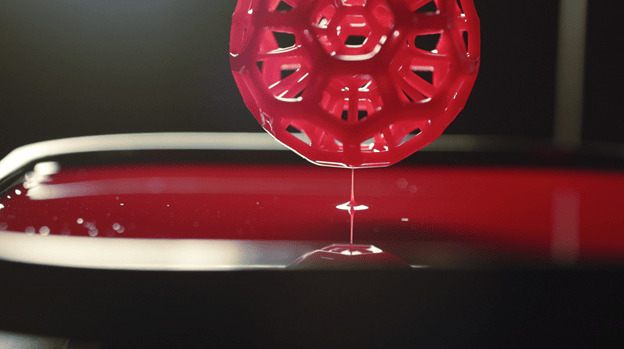
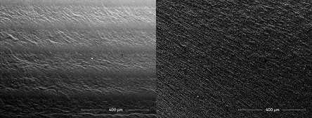
In CLIP™, liquid photopolymer resin is selectively exposed to a UV light source and is solidified into parts. Despite initial appearances, CLIP™ is unique from SLA and DLP as it is a truly continuous process that "grows" parts, removing the discrete steps of previous printing methods. CLIP™'s innovation lies in its oxygen-permeable membrane that creates a dead zone underneath the part (known as a persistent liquid interface), allowing for continuous curing as the part is drawn out of the resin. Instead of using a layer-by-layer approach, CLIP™ uses a digital projector and various microcontrollers to project an ever-changing picture of a 3D model, streamlining the print into a layer-less design (see Figure 1 below).

Image credit: DLS 3D Printing Technology | Carbon (carbon3d.com)
Figure 1: Layering effect from SLA/DLP printers (left) vs. virtually continuous surface from CLIP™ printers (right).
How does CLIP™ work?

Figure 2: Diagram of the functional components of a CLIP™ printer. Note this is a simplified diagram that may not fully represent real-world models.
This section will explore the workings of a CLIP™ printer to explain its differences over other vat polymerization technologies. Figure 2 shows the important components of CLIP™/DLS printers and their general arrangement, and we will use Figure 2 to briefly explain the functionality of each part, starting from the bottom up.
Light Engine/Projector
The projector, also known as the light engine, provides a curing light source for the print and is situated underneath the resin vat. The light engine projects a sequence of UV images through the vat and onto the build platform. Note that these images are not the discrete layers found in SLA/DLP light sources, but a changing sequence of cross-sectional images, leading to a layer-less print.
These light engines are like those found in DLP designs; they have a set resolution, are digitally projected, and cast a layer's worth of light at a given time. The difference between CLIP™ and DLP is that, though they have comparable resolutions, the CLIP™ process smoothly blurs the layers together and eliminates the so-called voxelated effect that is typically seen in DLP prints. Not only does this lead to excellent out-of-print finishes, but also faster build times and less post-processing work.
Photopolymer Vat & Oxygen-Permeable Window
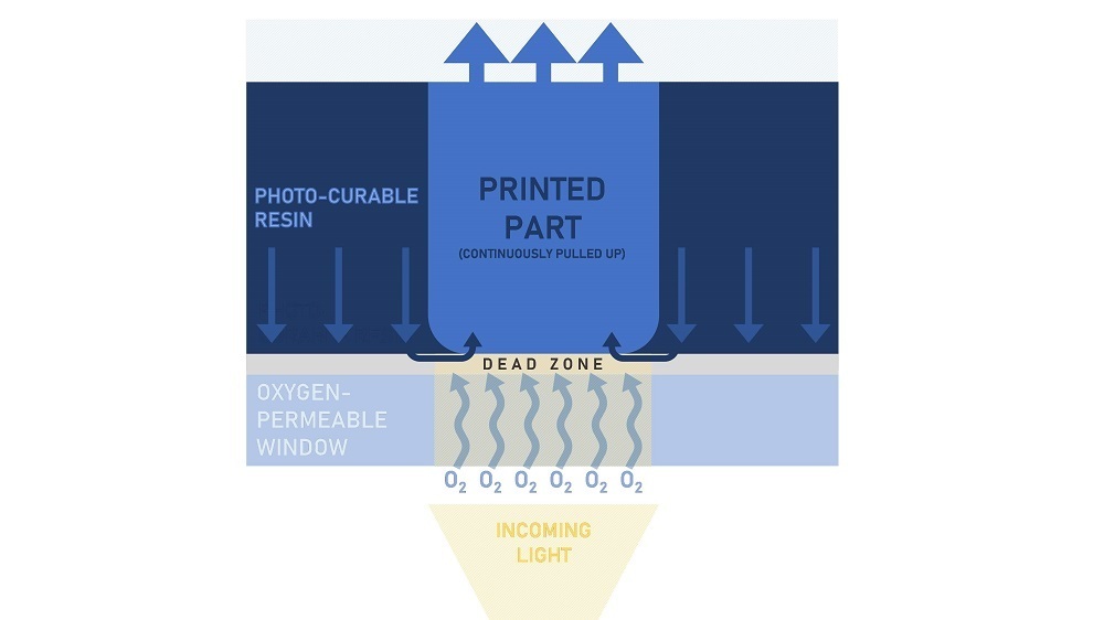
The photopolymer vat is the vessel where the UV-cured resin is held, and where the magic of CLIP™ printing takes place. Below, Figure 3 shows a close-up of the interface between the resin (dark blue) and the photopolymer vat (sky blue):

Figure 3: Cross-section close-up of the interfaces between the photopolymer vat and the printing resin. Note the dead zone, as well as the flow of arrows from the resin to the printed part.
The floor of the photopolymer vat is composed of a transparent oxygen-permeable window. This window allows both incoming light and oxygen to pass through to the resin. The oxygenated resin will not cure in the presence of light and forms a so-called "dead zone" of liquid resin that remains under the printed part.
This permeable membrane is the key component of CLIP™ technology; as the part is slowly raised out of the vat, the liquid dead zone allows the resin to flow under the part at a constant rate while preventing resin from curing on the window. The incoming light then cures the resin outside of the dead zone as the part is pulled up, creating the 3D print. Carbon 3D will not exactly divulge the chemistry of how this all works, but the result is a continually growing 3D printed part with no peeling or stopping necessary.
UV-Curable Resin
CLIP™ printers use thermosetting resin – or a polymeric liquid that solidifies in the presence of UV light. Though CLIP™ printers use similar materials to SLA/DLP designs, their unique printing process creates parts with enhanced surface finishes and mechanical properties and allows for more interesting materials. Below is a table that provides some examples of resins currently used in a CLIP™/DLS printer:
Table 1: Typical resins used in CLIP™ printing. Note this table is not exhaustive.
| Material | Material Name(s) |
| Rigid Polyurethane | RPU 70 |
| Urethane Methacrylate | UMA 90 |
| Impact-resistant epoxy | EPX 82 |
| High-Temp Cyanate Ester | CE 220, CE 221 |
| Flexible Polyurethane | FPU 50, FPU 230 |
| Elastomeric Polyurethane | EPU 40, EPU 60 |
| Elastomeric Silicone-Urethane | SIL 30 |
| Prototyping Resin | PR 25 |
Many resins require a mixture of two separate parts. Operators must calculate exactly how much resin they need, how much of each part they need, and how long their working time is before the resin becomes unusable. There is no re-using resin once it is mixed, so it is important to get the timing and ratios right before beginning the print.
The part is not yet finished after it has solidified. After the print, it must be cleaned of excess resin and any supports must be removed. Depending upon the material, a final thermal-post cure is needed to fully harden the part. This involves placing the part in an oven for an extended period (4-13 hours), where a secondary chemical reaction occurs, strengthening the part further.
Build Platform & Elevator
The build platform is the working space to which the resin adheres, and it is mounted to an elevator that controls the vertical (z-axis) movement of the part. The build platform starts partly submerged in the resin vat and is raised up via the elevator. The elevator is precisely controlled by the printer to keep resin flowing underneath the part, and is responsible for the "growing" effect of this 3D printer. These components are tied into an array of sensors and microprocessors to ensure the print is accurate and maintains structural integrity.
Advantages & Limitations of CLIP™
Emerging CLIP™ technology is an upgrade from more conventional 3D printers and is an incredibly promising additive manufacturing tool. This section will detail the advantages and disadvantages of CLIP™ technology.
The advantages of CLIP™ printing are as follows:
- CLIP™ prints have the accuracy and the surface quality of DLP/SLA prints but are completed 100 times faster.
- CLIP™ prints are layer-less, enhancing their surface finish to be comparable to injection-molded parts.
- Parts are watertight, fully isotropic (have strength in any orientation), and have increased strength over SLA/DLP prints.
- Parts can be used for functional prototyping and even for full production runs.
- The material choices for CLIP™/DLS printers are widely varied and unique to many other printer types.
The limitations of CLIP™ printing are as follows:
- Carbon3D's line of CLIP™/DLS printers can only be rented, and the printers themselves are very expensive to rent and train personnel on (upfront cost is $64,000+). The resin is also expensive ($99-$399 for each container).
- CLIP™ is still an emerging technology, so support is difficult to find and there are few options (if any) to choose from.
- CLIP™/DLS is still under active patent, so alternatives will not be available for a long time or until the rights are sold. Access to Carbon's rental program is also limited.
- While creating amazing, production-quality parts, investment in CLIP™ technology can be harder to justify at present given so many affordable 3D printers provide good results at lower price points.
Applications of DLP 3D Printing
CLIP™/DLS printers are used in applications that require mass customization and fast lead times. Such a versatile machine has nearly infinite applications, but the brief list below shows off some of its most well-known uses:
- Medical equipment/tools/impressions
- Footwear midsoles & athletic equipment
- Automotive parts
- Prototyping
- An alternative process to injection molding
- End-use functional parts & direct digital manufacturing
and much more.
Summary
This article presented an understanding of what continuous liquid interface production is and how it works. We hope this brief article showed the advanced capabilities of CLIP™ technology and how it can benefit your business. For more information on related products, consult our other guides or visit the Thomas Supplier Discovery Platform to locate potential sources of supply or view details on specific products.
Sources
- How Continuous Liquid Interface Production is Speeding Up the 3D Process (azom.com)
- AM 101: Digital Light Synthesis (DLS) | Additive Manufacturing
- Continuous Liquid Interface Production (CLIP™) - Dinsmore Inc.
- Carbon DLS - Xometry
- 3D Printing Guide - Xometry
- IRJET-V4I1003.pdf
- Bits to Atoms: How Carbon's CLIP™ 3D Printing Technology Works - Tested
- Layerless fabrication with continuous liquid interface production (pnas.org)
- CLIP™: The New Game-Changing Layerless 3D Printing Technology (designorate.com)
- DLS 3D Printing Technology | Carbon (carbon3d.com)
- SLA 3D Printer vs DLP 3D Printer vs DLS 3D Printer - MANUFACTUR3D (manufactur3dmag.com)
Copyright and Trademark Notices
- CLIP™ is a trademark of Carbon 3D Inc., Redwood City, CA
Other Types of 3D Printing
- All About Material Jetting 3D Printing
- All About Multi Jet Modeling (MJM) 3D Printing
- All About Fused Deposition Modeling (FDM) 3D Printing
- All About Stereolithography 3D Printing
- All About Photopolymerization 3D Printing
- All About Sheet Lamination/Laminated Object Manufacturing
- All About Electron Beam Additive Manufacturing
- All About Direct Energy Deposition 3D Printing
- All About Digital Light Processing (DLP) 3D Printing
Related Articles
- Top 3D Printing Services Companies in the USA
- Origins of 3D Printing and Additive Manufacturing
- Overview of 3D Printing Technologies
- Top 3D Printing Manufacturers and Suppliers (Publicly Traded and Privately-Owned)
- Top Suppliers of Additive Manufacturing Consulting Services
- The Best 3D Printers under $300
- The Best 3D Printers under $200
- The Best 3D Printing Software
- The Best 3D Printer Under $1000
- The Best 3D Printer Under $500
More from Custom Manufacturing & Fabricating
mcclintockwatty1988.blogspot.com
Source: https://www.thomasnet.com/articles/custom-manufacturing-fabricating/continuous-liquid-interface-production-3d-printing/

0 Response to "Different Stages of Continuous Liquid Interface Production"
Post a Comment